Home / Services / CFD & Thermal Consulting
High-Fidelity Flow & Heat Transfer Analysis

CFD & Thermal Consulting

We transform complex fluid-flow and heat-transfer problems into clear engineering decisions through CFD modelling, thermal validation, design optimisation and practical recommendations ready for product development.

CFD
Flow Fields
CHT
Thermal Coupling
DOE
Optimisation
QA
Validation
CFD Result Visual

Thermal-Fluid Result View

Engineering View
CFD airflow visual reference from Ansys

Review flow paths, pressure losses, heat-transfer behaviour and design actions through clear CFD result interpretation.

Pressure Drop
Reviewed
Hot Spots
Located
Design Action
Recommended
What The Service Means

We Do Not Just Run CFD — We Translate It Into Engineering Decisions

CFD, or computational fluid dynamics, uses numerical models to predict how liquids and gases move and how heat transfers through a product or system. In a consulting project, this means we can test airflow, pressure loss, cooling performance, thermal hot spots and design alternatives before expensive prototyping.

Our service covers the complete workflow: understanding your geometry and operating conditions, preparing the fluid domain, building the mesh, setting boundary conditions, solving the model, validating the results and converting contours into clear recommendations.

01 / Discover

Find the Cause

Identify why a component overheats, why a pressure drop is high, or why airflow is not reaching the right region.

02 / Compare

Test Alternatives

Compare ducts, fans, heat sinks, battery cooling layouts, enclosure vents and design variants before manufacturing.

03 / Optimise

Improve Performance

Reduce thermal risk, improve flow uniformity, lower losses and increase reliability using parametric CFD studies.

04 / Deliver

Report Clearly

Receive a professional report with assumptions, setup, annotated images, result tables and practical recommendations.

Service Capabilities

What We Can Solve

From early design screening to detailed validation, each service is structured to provide useful engineering outputs rather than just colourful contours.

Internal & Flow Field

Velocity fields, recirculation, pressure drop, flow separation, wake behaviour and flow uniformity assessment.

Thermal Management

Electronics cooling, heat sinks, battery packs, natural/forced convection and conjugate heat-transfer modelling.

Aerodynamics & Wind Loading

Drag, lift, cooling flow, wind effects, enclosure ventilation and aerodynamic optimisation for moving or stationary systems.

Porous Media & Filters

Pressure-loss coefficients, permeability effects, flow distribution, filter behaviour and porous thermal performance.

Heat Exchangers & Ducts

Flow balancing, thermal effectiveness, fan operating points, duct redesign and pressure-loss reduction.

Design Optimisation

Parametric studies, DOE matrices, sensitivity charts and recommendations that convert simulation results into design changes.

CFD Service Workflow

CFD Workflow, Visual References & Engineering Decisions

Embedded media and visual references explain how CFD translates flow and thermal behaviour into practical engineering decisions.

What The Service Means

CFD turns flow and heat problems into visible engineering decisions.

Computational Fluid Dynamics is used to predict how liquids, gases and heat move through a product or environment. Instead of relying only on prototypes, we build a virtual model, define the physics, solve the case and convert the results into clear recommendations.

We use CFD results to explain pressure drop, velocity distribution, recirculation, hot spots, thermal margins, airflow balance and cooling performance through clear visuals and concise engineering reports.

The final value is a practical design recommendation: which option runs cooler, which duct reduces pressure loss, which fan layout performs better and which geometry should move forward.
01
Model Setup
02
Solve Physics
03
Recommend
Official Ansys Learning Reference

Intro to Ansys Fluent

This video introduces the CFD workflow, from the fundamentals of Fluent to setup steps and result interpretation that support engineering decisions.

Open video source →
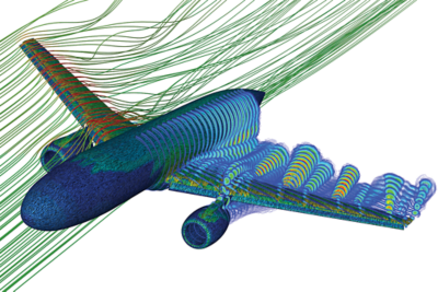
CFD streamlines around aircraft wing from Ansys visual reference
Flow Prediction

Velocity, wake behaviour and aerodynamic flow paths

We use CFD visuals like streamlines and contours to explain where flow accelerates, separates or recirculates, then connect those results to design changes.

Service Message

Service value

CFD consulting covers problem definition, simulation setup, post-processing, design comparison and final engineering recommendations.

Pressure drop and airflow balancing
Thermal hot-spot and cooling checks
Design alternatives and optimisation
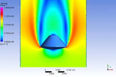
Ansys Fluent velocity contour simulation
CFD Basics

Velocity & Pressure Contours

CFD makes hidden flow behaviour measurable, comparable and easy to communicate.

Official source →
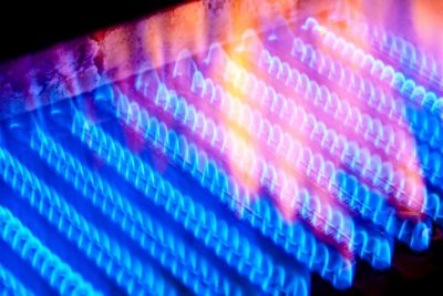
Ansys Fluent heat transfer tutorial visual
Thermal CFD

Heat Transfer Studies

Review conduction, convection, temperature gradients and thermal boundary-condition effects.

Official source →
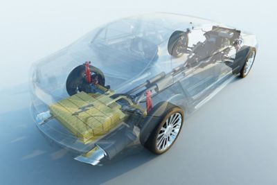
Battery thermal management simulation visual from Ansys
Battery Cooling

Battery Thermal Management

Evaluate temperature spread, cooling strategy and thermal safety in battery packs and modules.

Official source →
Heat exchanger simulation visual from Ansys
Heat Exchanger

Heat Exchangers & Ducts

Assess thermal effectiveness, pressure loss, flow distribution and geometry improvement.

Official source →
Video Playlist

Fluent Workflow Videos

Embedded workflow videos help clients review the simulation process within the service workflow.

Open playlist →
Consulting Workflow

A Clear Process From Problem to Decision

Each CFD engagement includes documented assumptions, boundary conditions, mesh controls, convergence behaviour and final engineering interpretation.

Typical Output

A concise engineering report, annotated images, result tables, design recommendations and source files when required.

01

Problem Definition

We review geometry, operating conditions, objectives, acceptable assumptions and the exact decision the simulation needs to support.

02

Geometry Preparation & Meshing

We clean CAD geometry, define fluid regions, create boundary named selections and generate a mesh suitable for the target physics.

03

Solver Setup & Validation

Boundary conditions, material properties, turbulence models, heat sources and convergence criteria are configured and checked.

04

Result Interpretation

Contours are converted into engineering insight: why losses happen, where hot spots form, and which changes provide the best improvement.

05

Optimisation & Final Report

We compare design alternatives, summarise trade-offs and deliver practical recommendations for prototypes, manufacturing or further testing.

Applications

Typical Projects

Battery thermal management
LED and electronics cooling
Heat exchanger improvement
HVAC and ventilation flow
Porous media pressure drop
Aerodynamic drag reduction
Pump, duct and manifold losses
Natural convection studies
Deliverables

What You Receive

Engineering Report

Assumptions, model setup, result interpretation and design recommendations.

Annotated Results

Temperature, velocity, pressure, streamlines and key comparison plots.

Design Direction

Actionable changes ranked by impact, practicality and expected performance gain.

Ready to Start?

Turn Your Thermal or Flow Problem Into a Clear Design Decision

Send your geometry, operating conditions, objectives and any available test data. We will help define the right simulation scope and deliver professional CFD insight.

Use these examples to define the right CFD scope, boundary conditions, result outputs and validation approach for your project.

Request a Quote