Home /Software /Proteus & EasyEDA

Proteus & EasyEDA Embedded Electronics Projects

Browse two electronics design case studies in an interactive portfolio style, with selectable project sections, hover previews, circuit screenshots, hardware images and smooth image zoom.

Room Temperature Control
Proteus temperature-control preview

Raspberry Pi + DHT22 + Relay

Adaptive fan control at 25°C with LCD feedback and Proteus validation.

Smart Door Alert
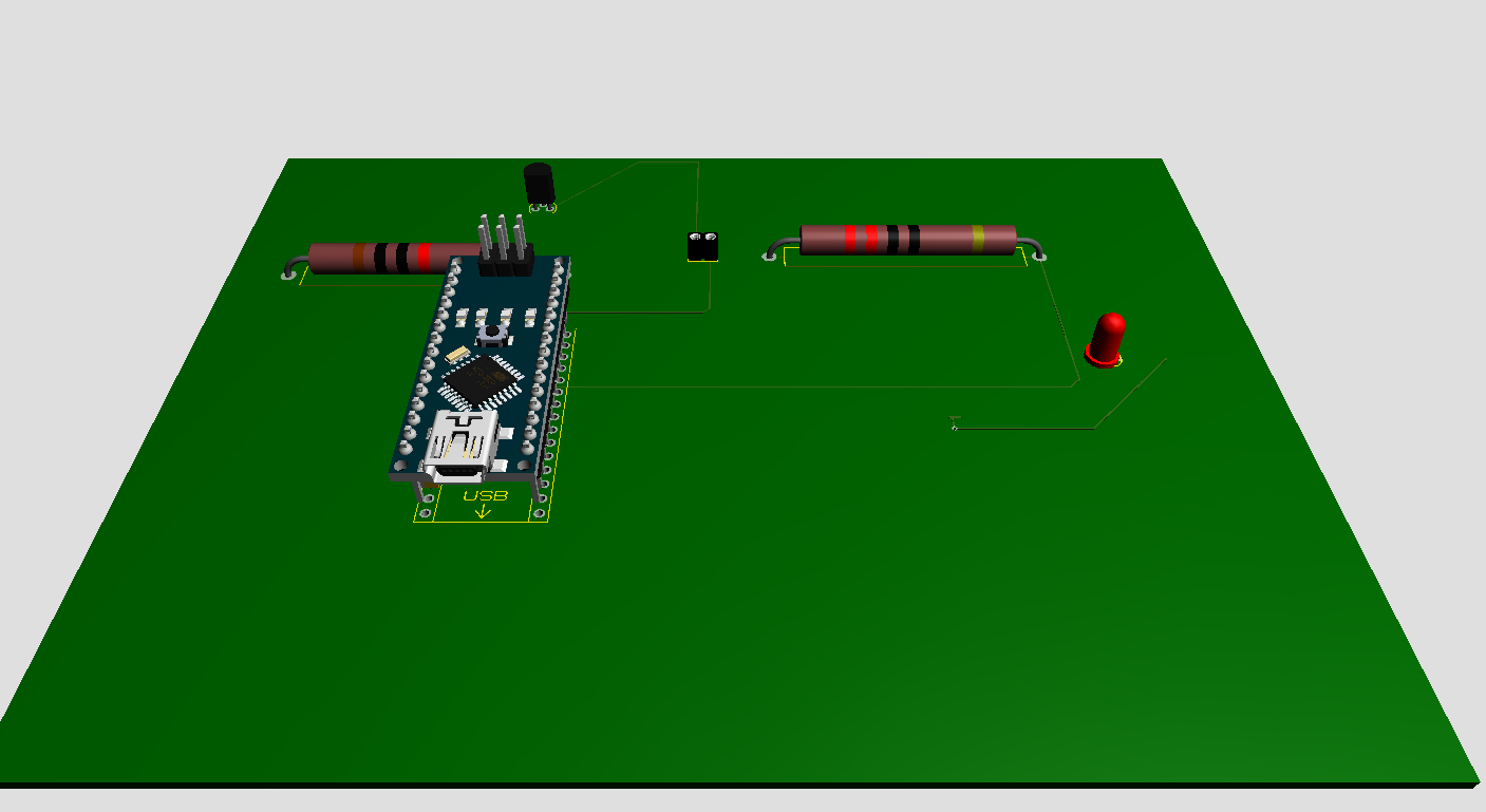
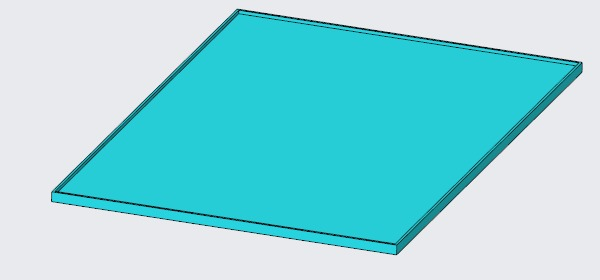
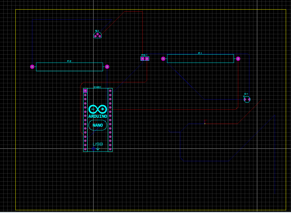
Smart door alert PCB preview

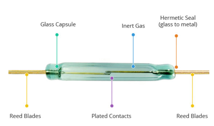
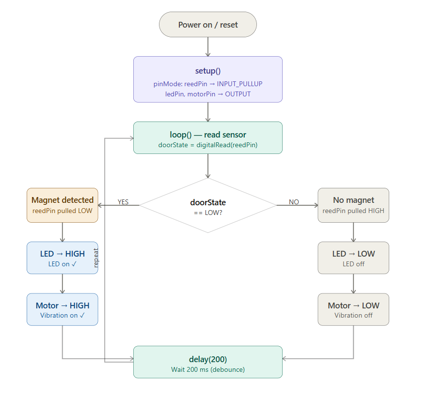
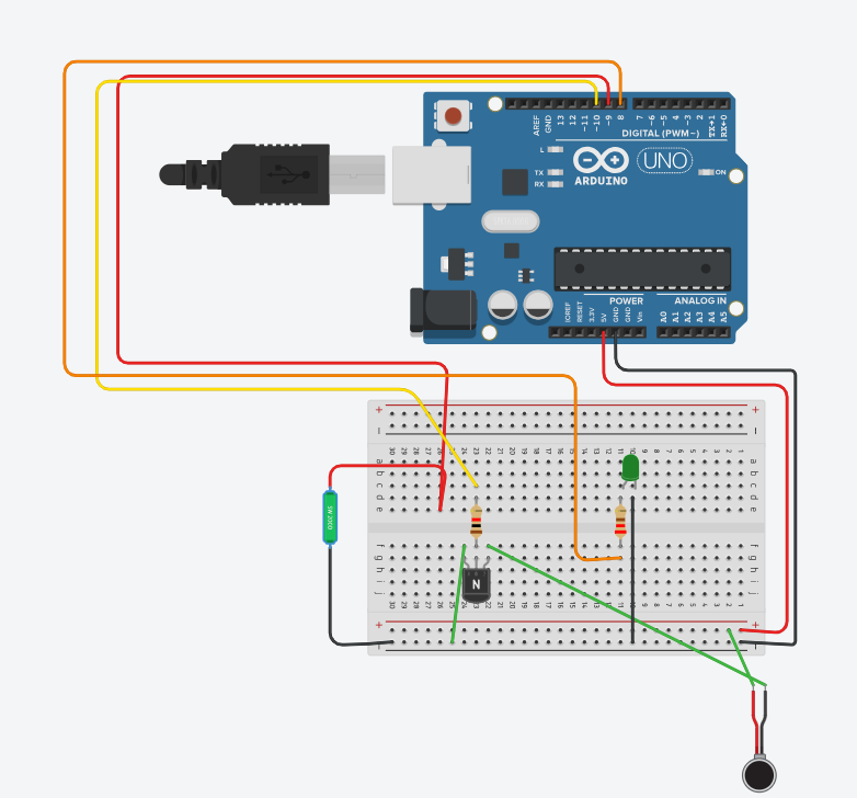
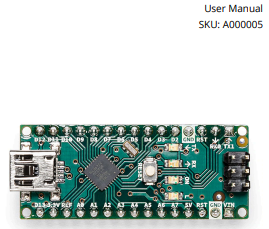
Arduino Nano + Reed Switch

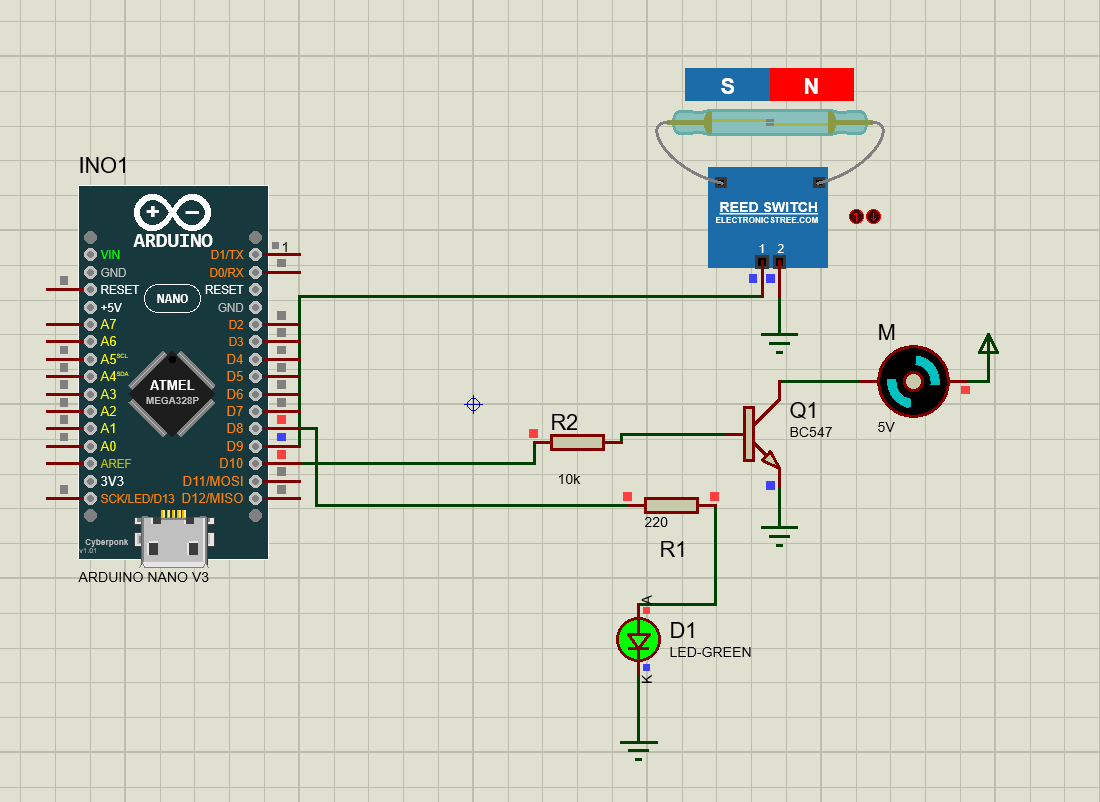
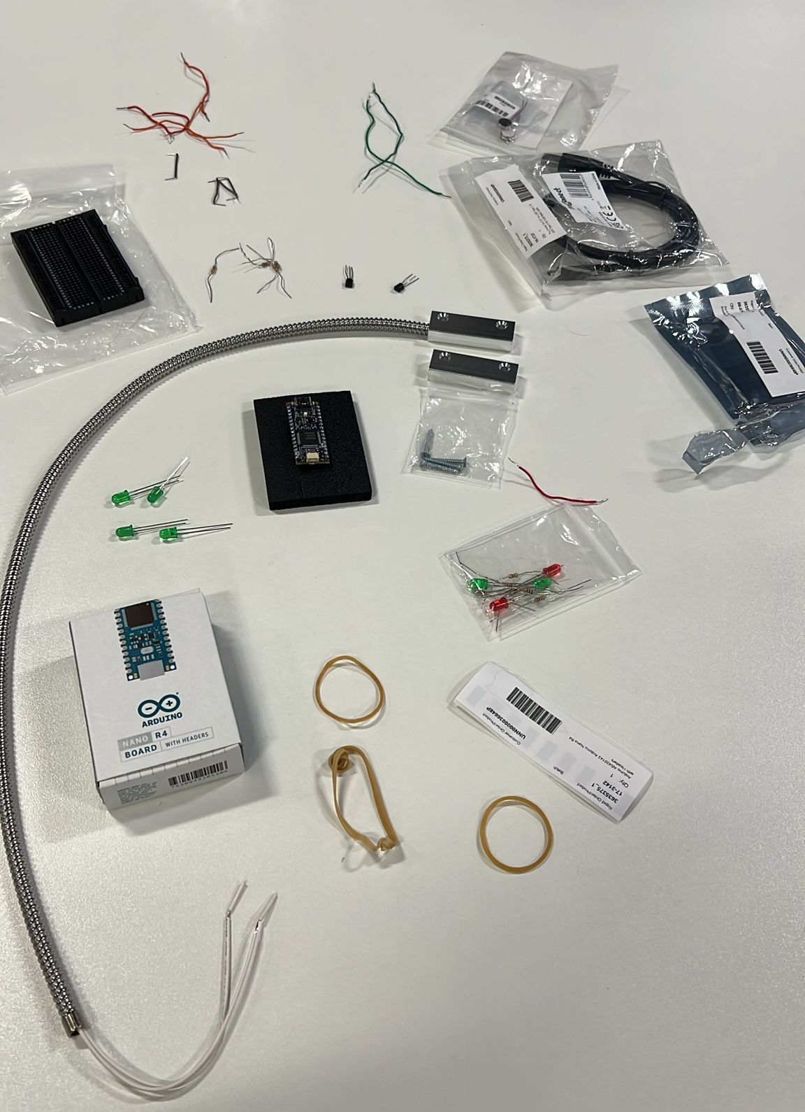
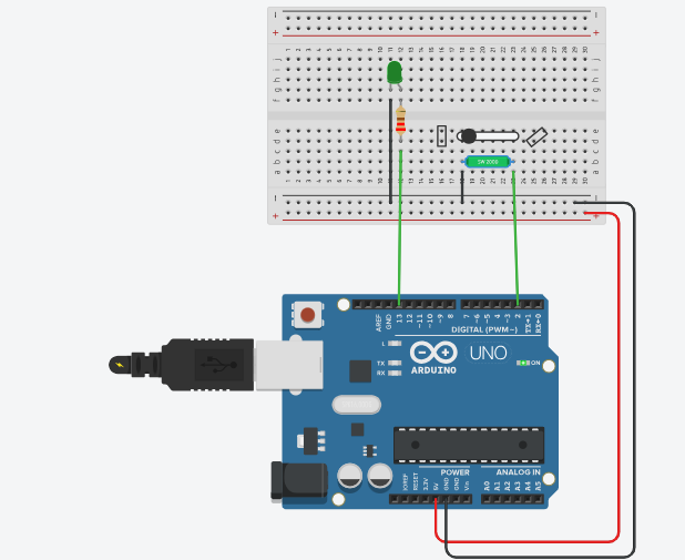
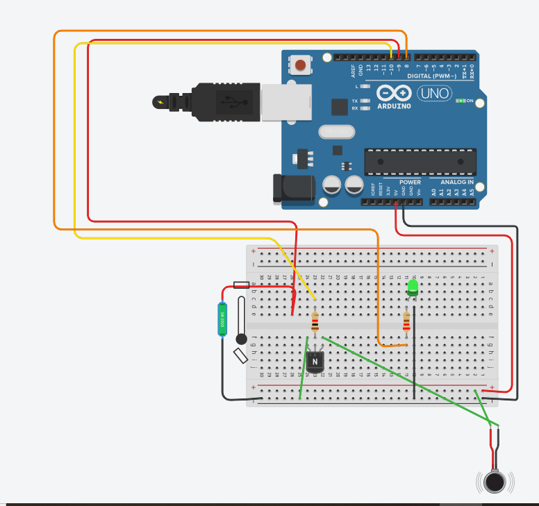
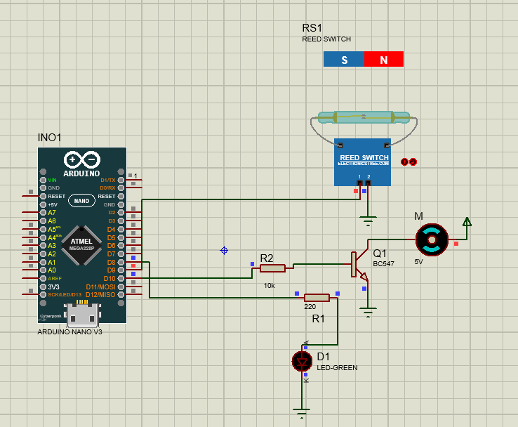
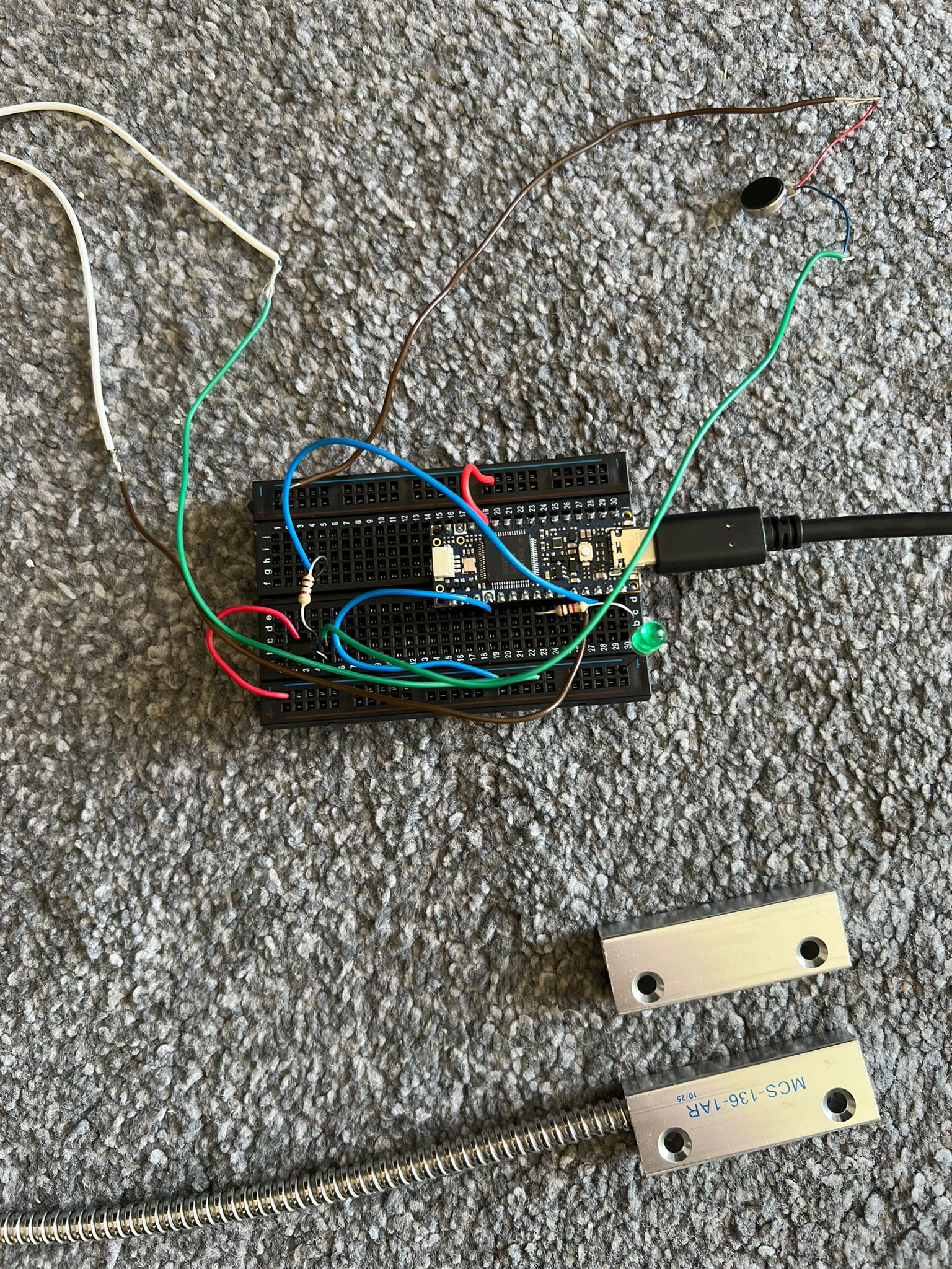
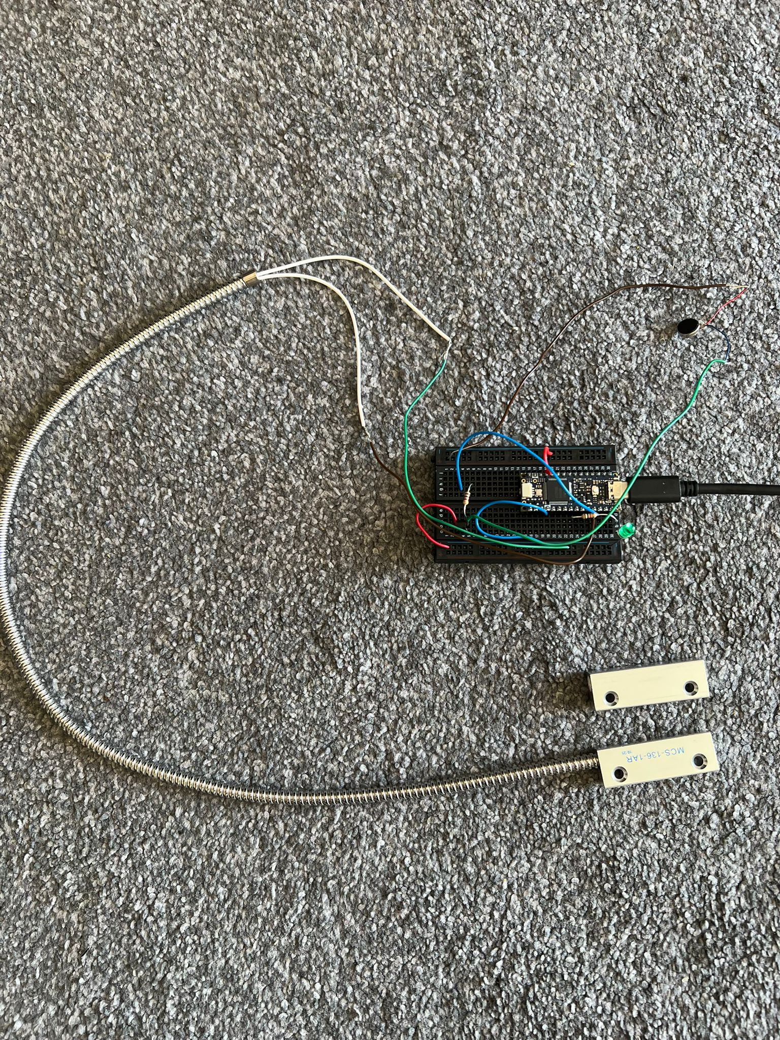
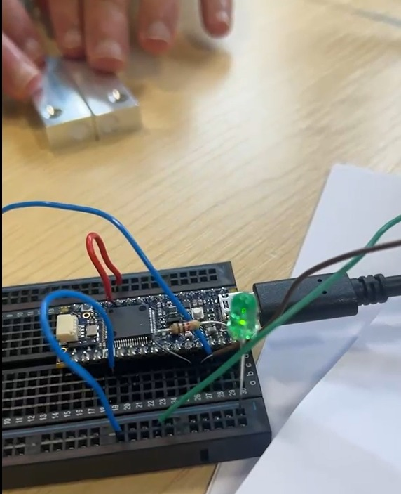
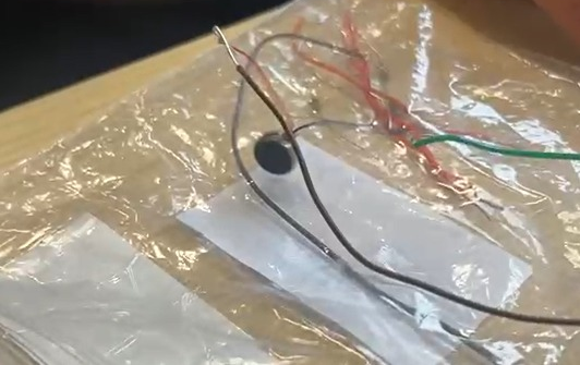
Visual LED and tactile motor alert system with TinkerCAD, Proteus and PCB layout.
EW1058 Hamad Project Draft

Intelligent Room Temperature Measurement & Control

A smart climate-control prototype built around Raspberry Pi, DHT22 temperature/humidity sensing, LCD status display and relay-driven fan control. The system regulates comfort around a 25°C set point while using Proteus simulation to validate the circuit before hardware implementation.

25°C
Target set point
DHT22
Temp / humidity
LCD
Real-time status
Relay
Fan switching
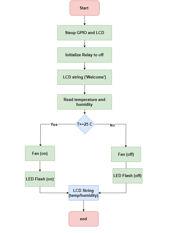
Temperature control flowchart
Step 01

Control Logic and System Flow

The workflow starts by setting up GPIO pins and the LCD, keeping the relay off, then reading temperature and humidity. When the temperature reaches or exceeds 25°C, the relay activates the fan and the LCD updates the user with live temperature and humidity information.

Temperature control system flowchart
Step 02

Hardware Architecture

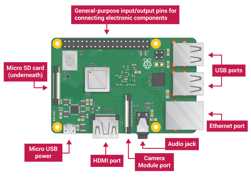
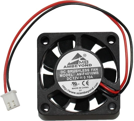
The Raspberry Pi acts as the controller, reading sensor data and driving the LCD, LED and relay outputs. The hardware set also includes DHT22 sensing, a brushless DC fan, a Songle relay, resistors and jumper wiring for quick prototyping.

Raspberry Pi layout
Step 03

Sensing and Display Interface

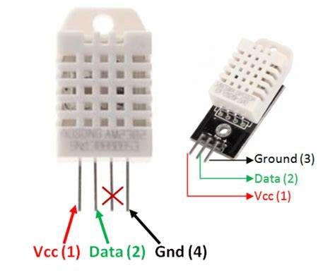
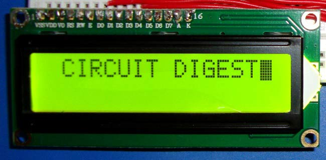
The DHT22 supplies digital temperature and humidity data while the 16x2 LCD provides a direct local interface. This makes the prototype readable without an external computer and supports immediate feedback during testing.

DHT22 temperature sensor
Step 04

Relay-Controlled Fan Output

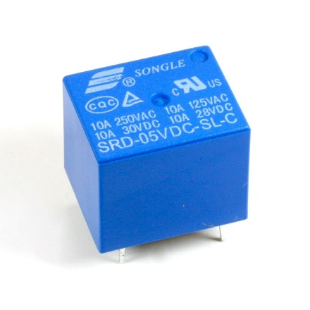
A relay interface is used to switch the fan according to the control algorithm. This separates the low-current Raspberry Pi GPIO logic from the higher-current fan output and makes the design safer for actuation.

Relay module used for fan switching
Step 05

Proteus Circuit Validation

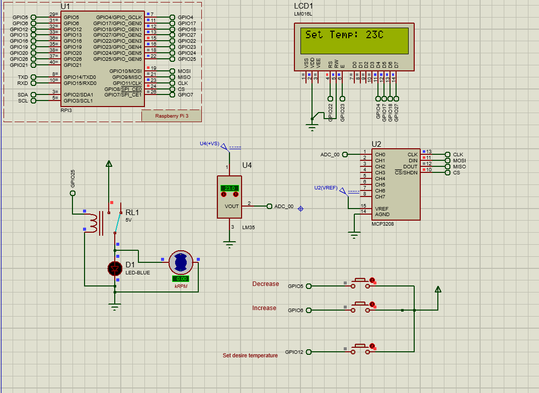
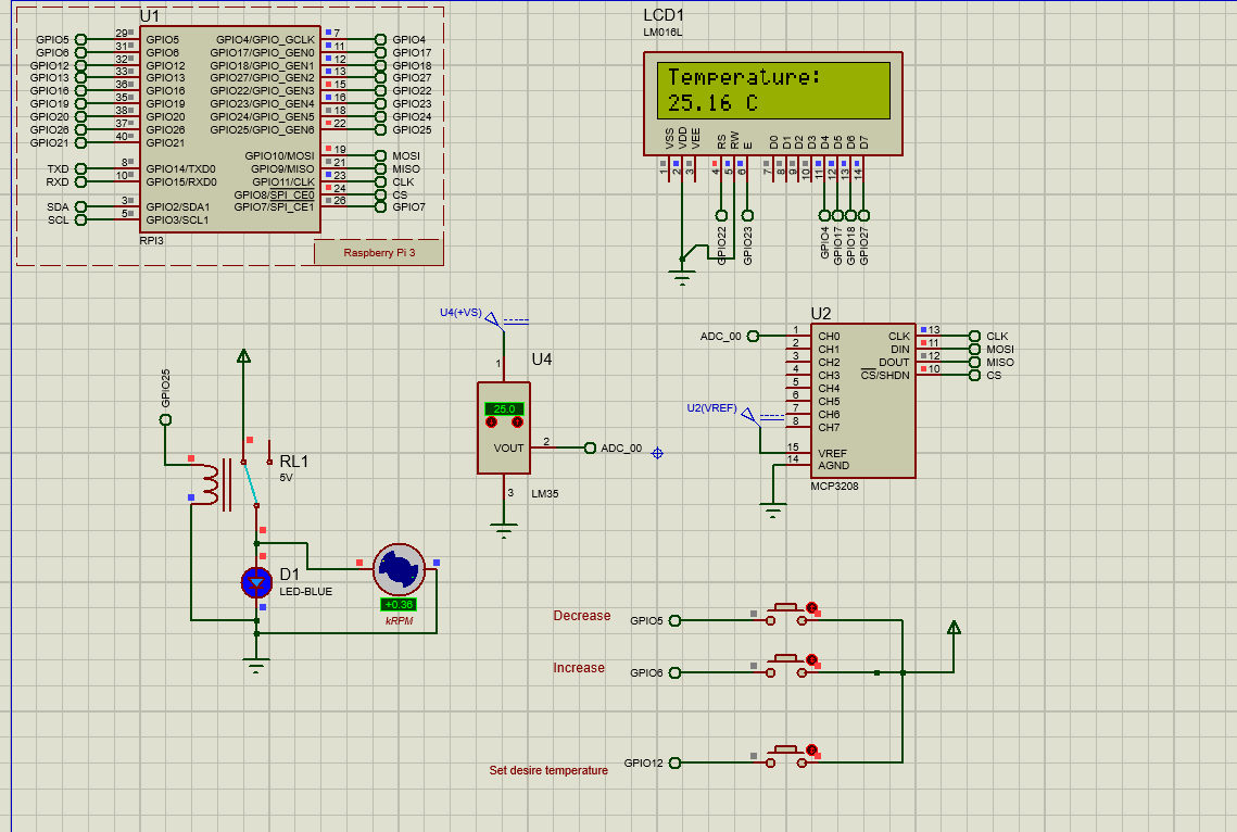
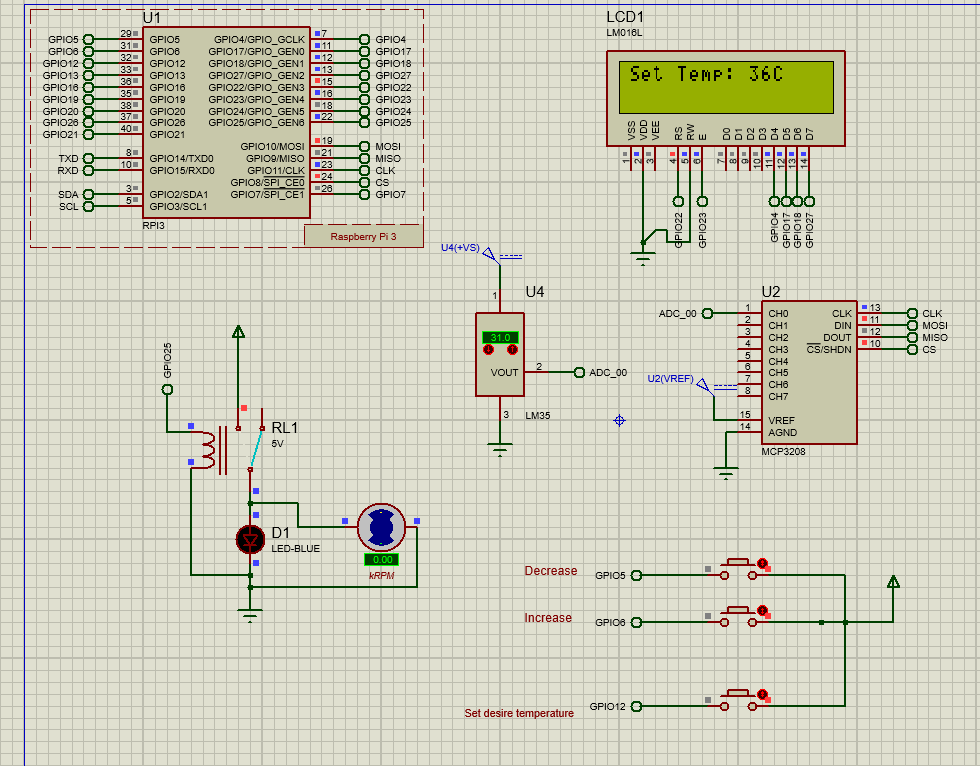
The Proteus schematic validates the Raspberry Pi-based temperature-control circuit, including LCD display, button inputs, sensor-conditioning elements and fan-output behaviour before physical implementation.

Proteus simulation schematic
Step 06

Hardware and Software Output

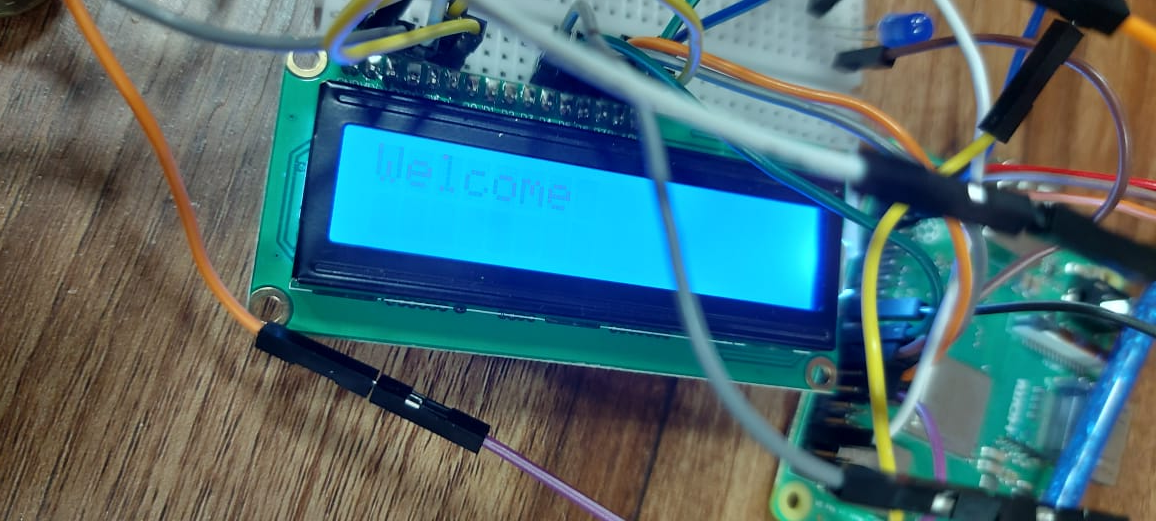
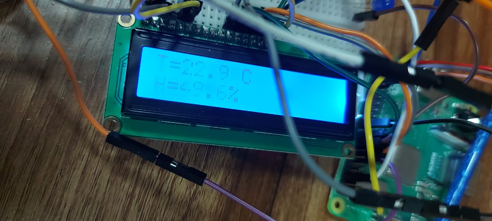
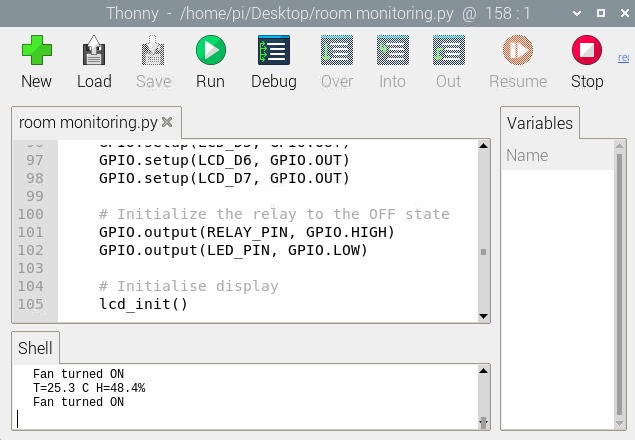
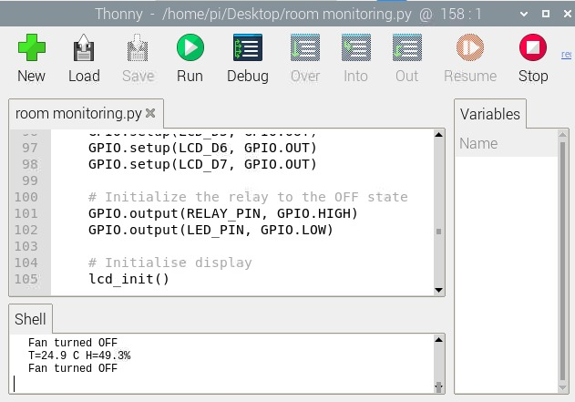
The implemented prototype demonstrates live LCD output and script execution. The Python program configures GPIO, reads the sensor or ADC channel, updates the desired temperature and controls the relay and LED feedback loop.

Hardware LCD output
Project Gallery

Additional Temperature-Control Images

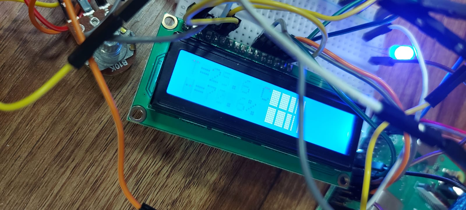
Extra images from the report show the LCD, Proteus execution states, component references and simulation code used to check the embedded control workflow.

PCB project gallery image PCB project gallery image PCB project gallery image PCB project gallery image PCB project gallery image PCB project gallery image PCB project gallery image PCB project gallery image