Home /Software /ANSYS Maxwell & JMAG

Maxwell & JMAG Electromagnetic Projects

Explore electromagnetic machine design and finite-element validation workflows, including analytical sizing, JMAG geometry construction, no-load back-EMF checks and torque verification for a high-speed permanent-magnet motor.

30 kW High-Speed PM Motor
JMAG Designer / Electromagnetic FEA

30 kW High-Speed SPM Motor Validation

A complete analytical sizing and JMAG finite-element validation workflow for a 3-phase surface-mounted permanent-magnet synchronous motor rated at 30 kW and 14,000 rpm. The model links classical electromagnetic sizing with geometry construction, back-EMF simulation and torque verification.

30 kW
Rated Power
14,000 rpm
Max Speed
325 V
DC Link
10 Poles
SPM Topology
12 Slots
Winding Layout
≈20 Nm
FEA Torque
JMAG complete cross-section of high-speed permanent magnet motor
Step 01

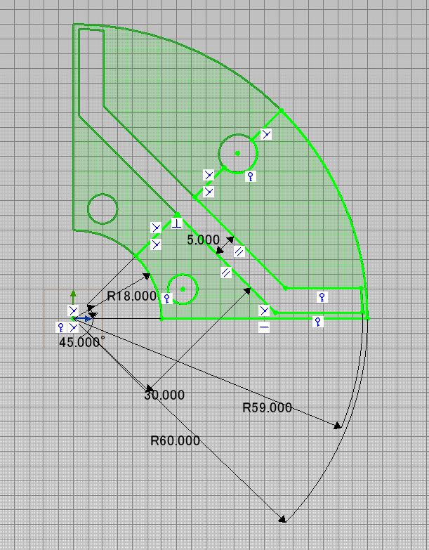
Dimensioned JMAG Sector Geometry

The analytical motor dimensions were rebuilt as a fully constrained sector inside JMAG Designer. This view defines the rotor radius, air gap, magnet arc, slot boundary and dimensional references required for repeatable electromagnetic modelling.

Annotated JMAG sector sketch with dimensions
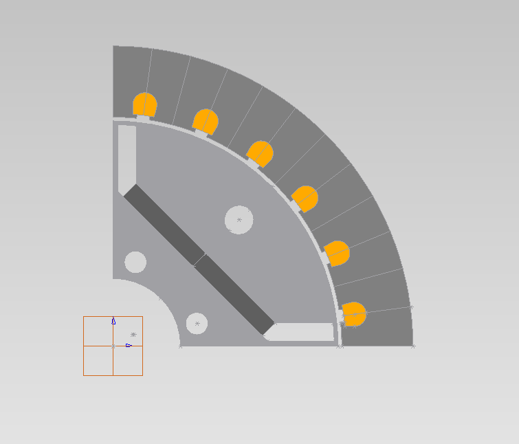
Quarter replicated JMAG motor cross-section
Step 02

Quarter Motor Replication

The constrained sector was replicated around the circumference to create a quarter-machine model. This confirms the repeating slot, tooth, magnet and air-gap layout before assembling the full two-dimensional motor cross-section.

Step 03

Full 2-D Cross-Section Assembly

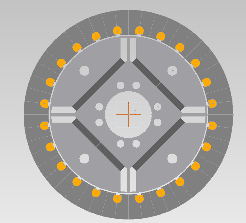
The full JMAG motor cross-section captures the surface-mounted permanent magnets, rotor core, stator slots, winding regions and air-gap path needed for the transient electromagnetic validation study.

Full 2D motor cross-section prepared for JMAG simulation
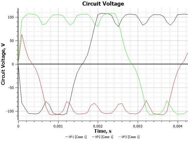
Three-phase no-load back-EMF waveform from JMAG simulation
Step 04

Three-Phase No-Load Back-EMF

The transient simulation verifies the induced three-phase voltage waveform at the rated speed of 14,000 rpm. The balanced phase displacement provides a validation check for the winding layout, pole count and air-gap flux assumptions.

Step 05

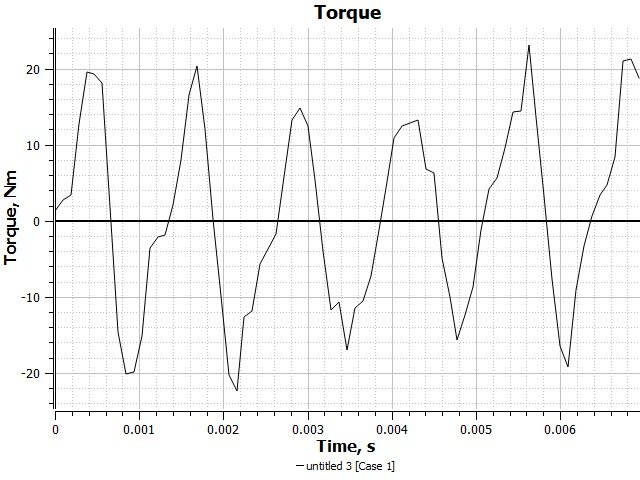
Torque Ripple and Rated Output Check

The simulated electromagnetic torque waveform is compared with the analytical torque requirement. The close average torque agreement confirms that the selected magnetic loading and electric loading are suitable for the target 30 kW high-speed motor rating.

JMAG electromagnetic torque waveform at rated speed
Result Gallery

JMAG Design and Validation Views

A clean visual set showing the dimensioned JMAG sector, replicated motor geometry, full cross-section, three-phase back-EMF waveform and torque response used to validate the high-speed permanent-magnet motor design.

JMAG annotated sector geometry JMAG quarter cross-section JMAG full motor assembly Back EMF simulation plot Torque simulation plot