Home /Software /CST Studio Suite

CST Studio Suite Electromagnetic Projects

Selected RF, microwave and terahertz simulation projects developed in CST Studio Suite, including antennas, metamaterials, absorbers, field plots, S-parameter validation and impedance matching workflows.

CSSR Patch Antenna
Microstrip Patch + CSSR preview

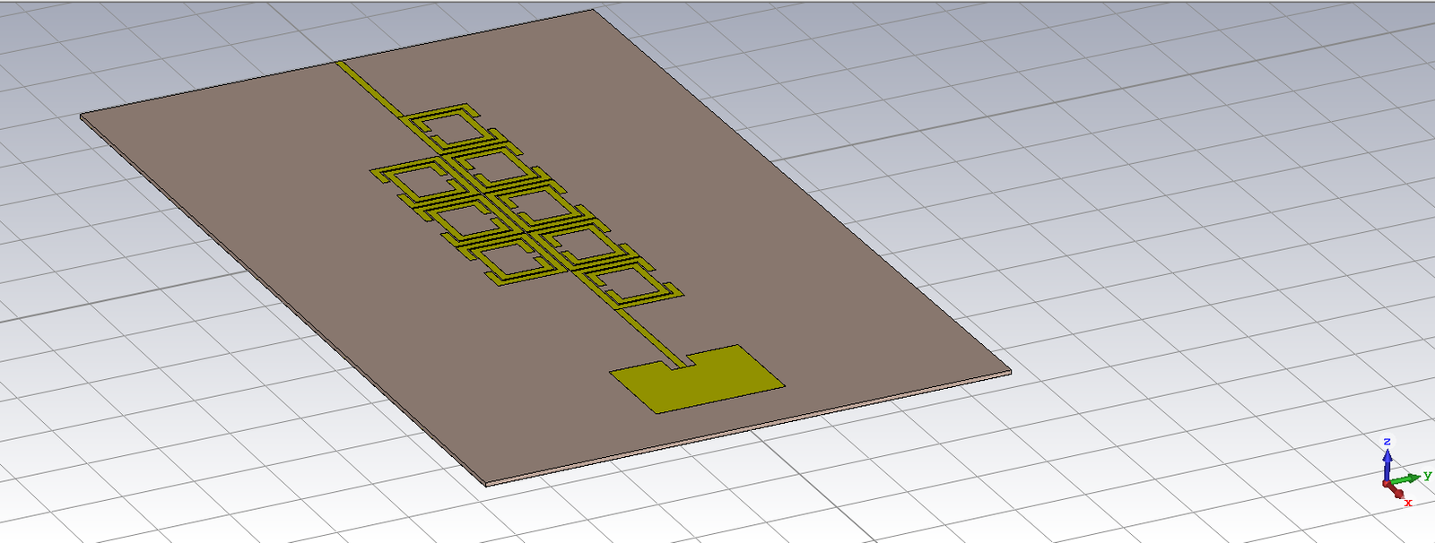
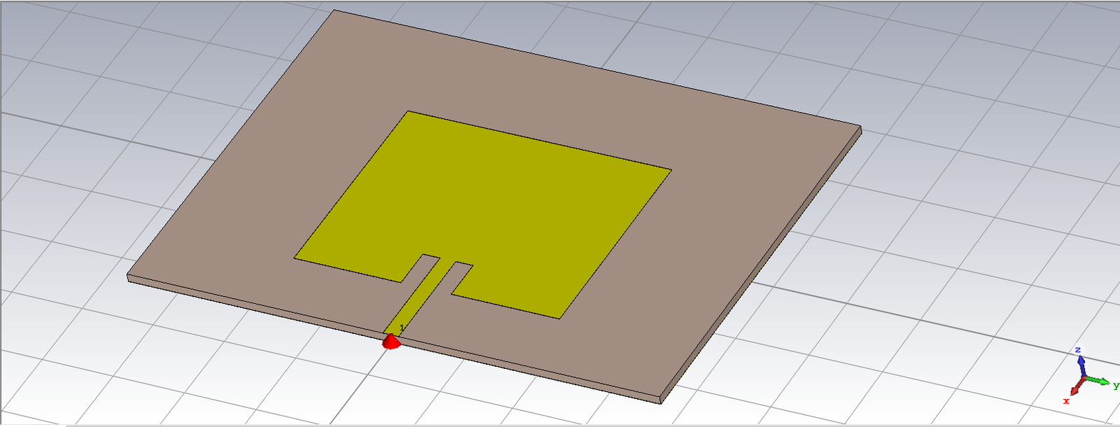
Microstrip Patch + CSSR

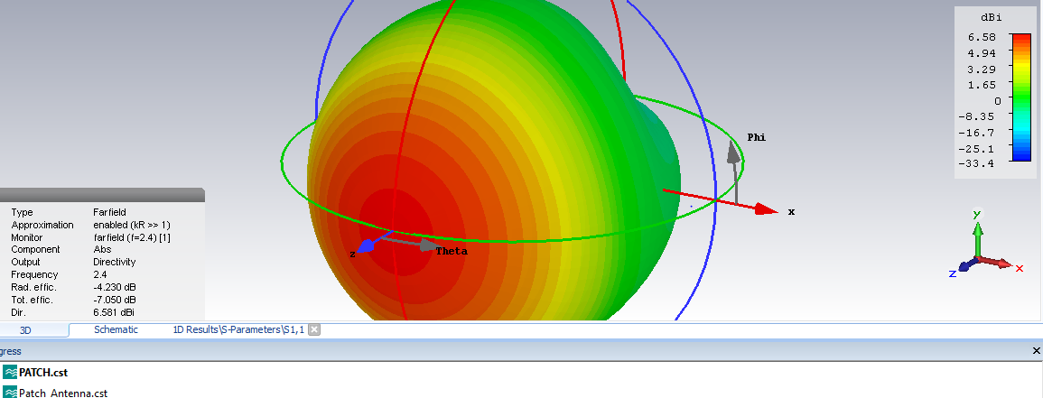
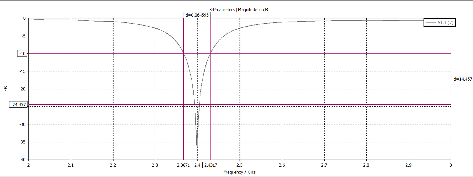
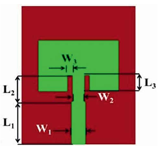
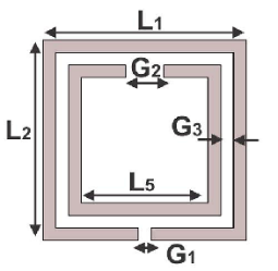
Patch antenna geometry, CSSR feed network, far-field and return-loss comparison.

THz Bow-Tie Antenna
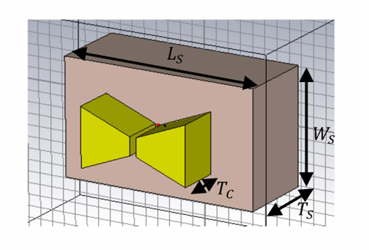
Photoconductive THz Antenna preview

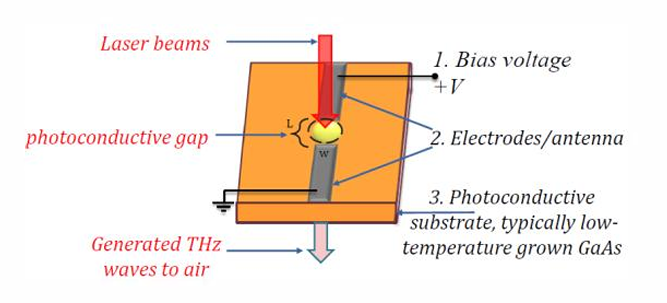
Photoconductive THz Antenna

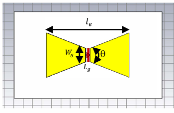
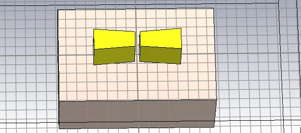
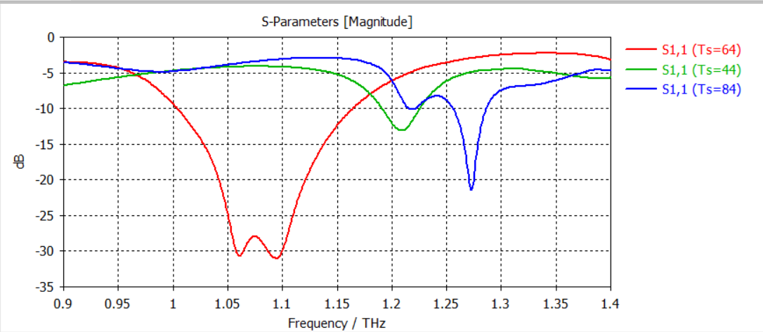
Bow-tie geometry, CST parameterisation and S-parameter sweeps.

VO₂ THz Absorber
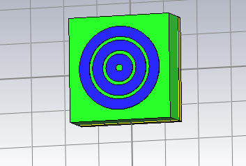
VO₂ Broadband Absorber preview

VO₂ Broadband Absorber

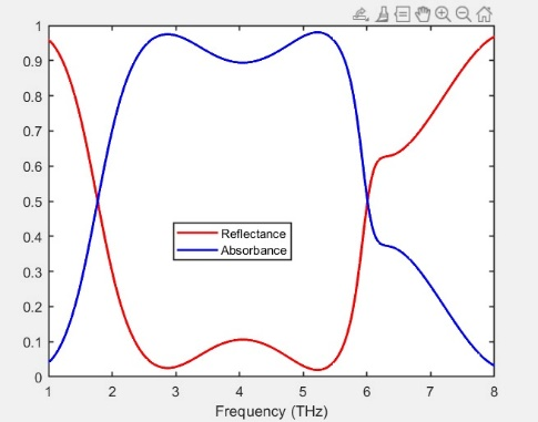
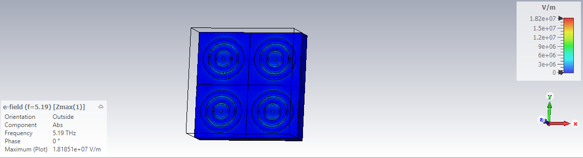
Spiral resonator geometry, absorbance curve and CST field maps.

Triple-Band THz Cell
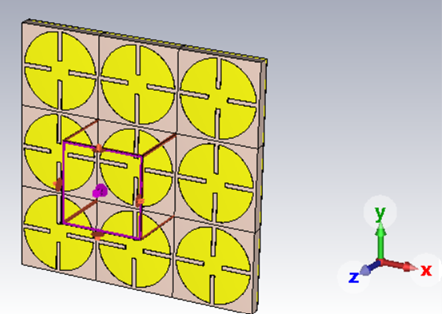
Triple-Band Resonator preview

Triple-Band Resonator

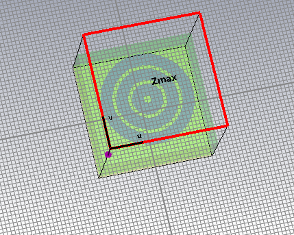
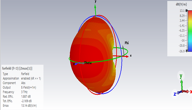
Unit-cell geometry, absorber peaks, 3D array and far-field visualization.

Square SRR THz
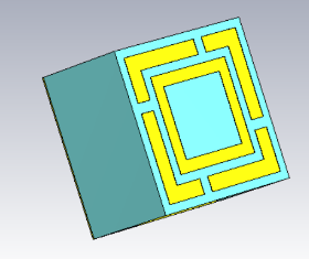
Square SRR THz Sensor preview

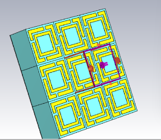
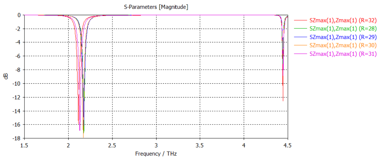
Square SRR THz Sensor

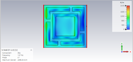
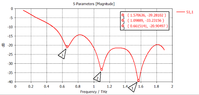
Layered SRR geometry, field maps and multi-parameter S11 plots.

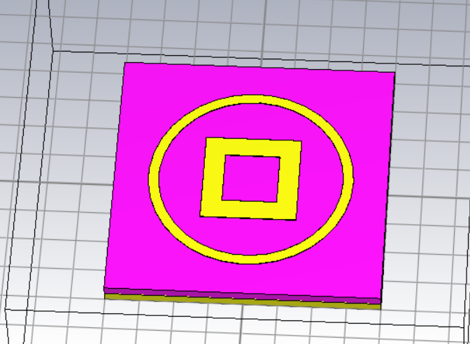
Dual-Band Absorber
Dual-Band THz Absorber preview

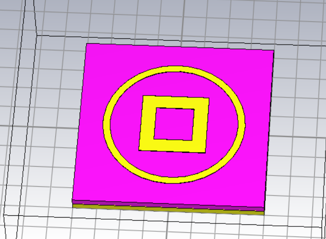
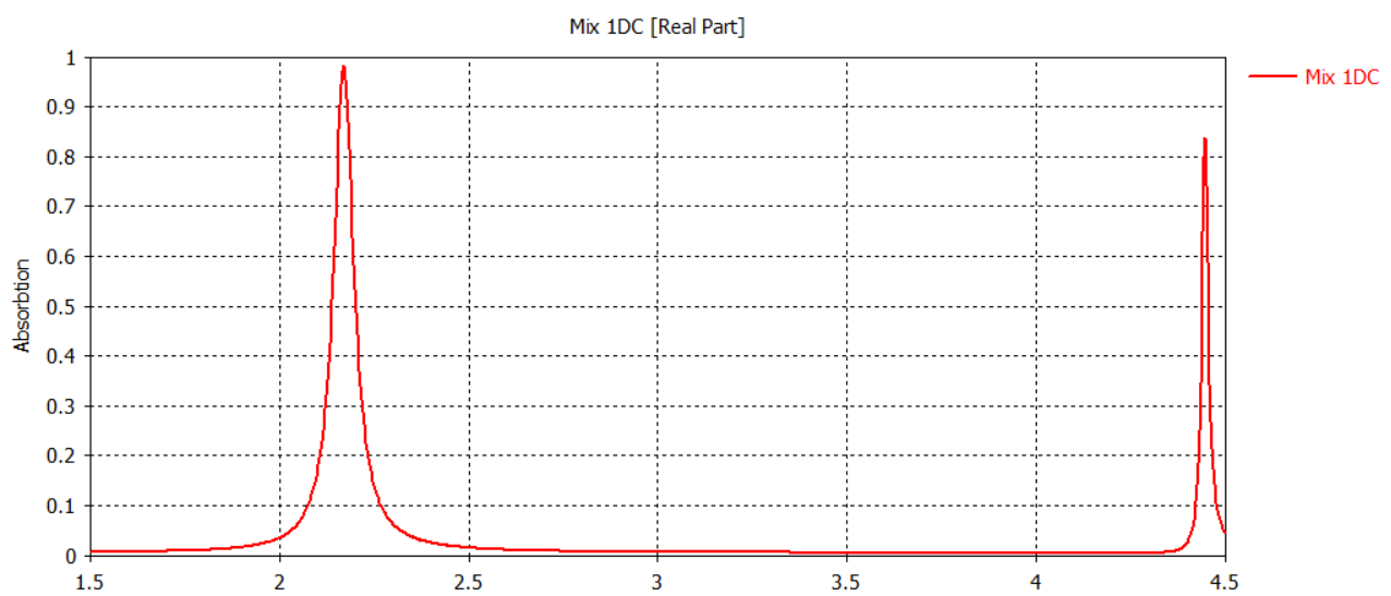
Dual-Band THz Absorber

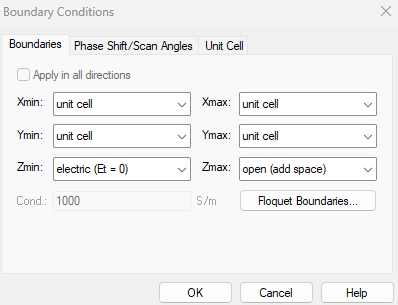
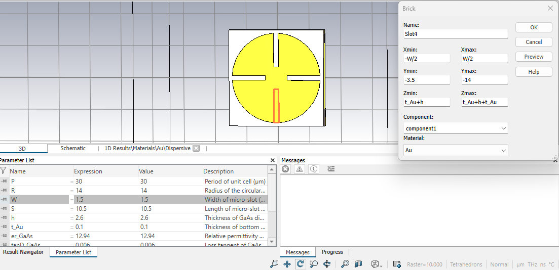
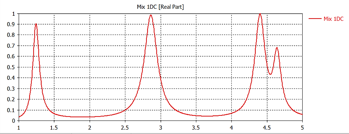
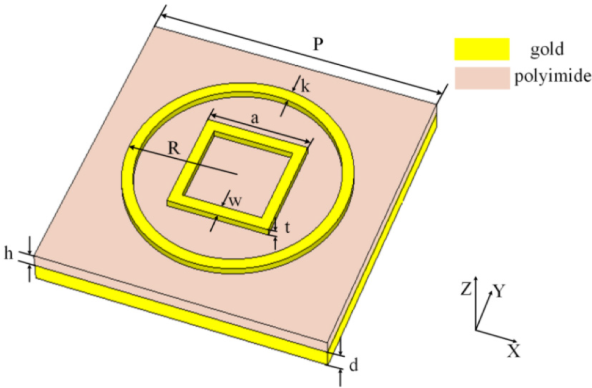
Absorber unit cell, CST model and dual resonance curves.

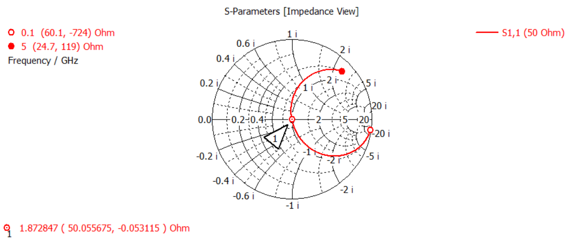
Impedance Matching
Smith Chart Matching preview

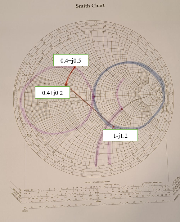
Smith Chart Matching

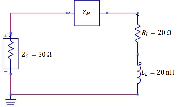
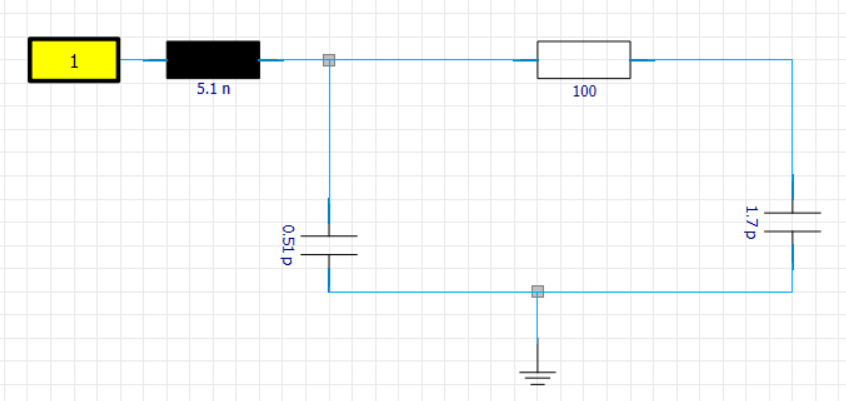
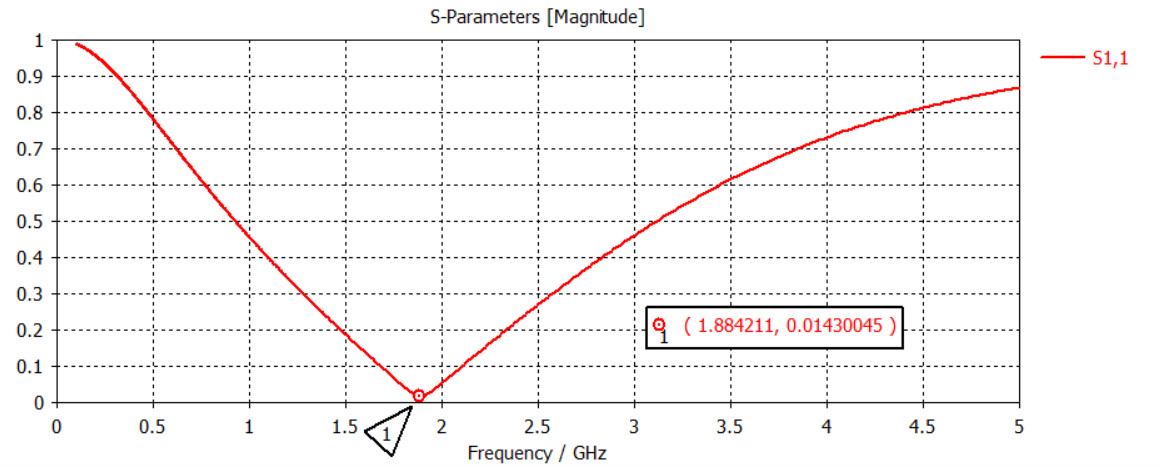
L-section network, Smith chart, CST schematic and low-S11 validation.
C367 Final Project Report

CSSR-Loaded Microstrip Patch Antenna Bandwidth and Return-Loss Enhancement

A CST Studio Suite project investigating how complementary split-spiral resonator loading changes a microstrip patch antenna response, including feed design, radiation pattern, S11 and VSWR behaviour.

CSSR-Loaded Microstrip Patch Antenna
Step 01

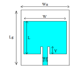
Conventional Patch Geometry

The baseline rectangular microstrip patch was created with substrate, ground plane and feed dimensions before introducing CSSR loading.

Conventional Patch Geometry
Step 02

CSSR Feed-Network Integration

The complementary split-spiral resonator was added to study additional resonant behaviour and improve the antenna bandwidth response.

CSSR Feed-Network Integration
Step 03

Radiation Pattern Evaluation

CST far-field results were used to inspect the radiation pattern and gain of the antenna after modelling and excitation.

Radiation Pattern Evaluation
Step 04

Return-Loss and VSWR Results

The final frequency-domain plots compare the S11 return loss and matching behaviour of the CSSR-loaded antenna configuration.

Return-Loss and VSWR Results